
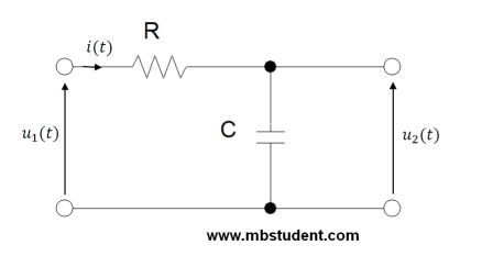
A state space representation and a transfer function designating for a low-pass filter. The Low-pass filter is an electric circuit which contains a resistor and a capacitor. The Resistor and the capacitor are connected in series. The input voltage (the input signal) is between resistor and capacitor. The output voltage (the output signal) is the capacitor's voltage. A one of capacitor's terminals is connected to the ground.
For the RC circuit shown above a dynamic model will be created. To be more precise, two dynamic models will be created:
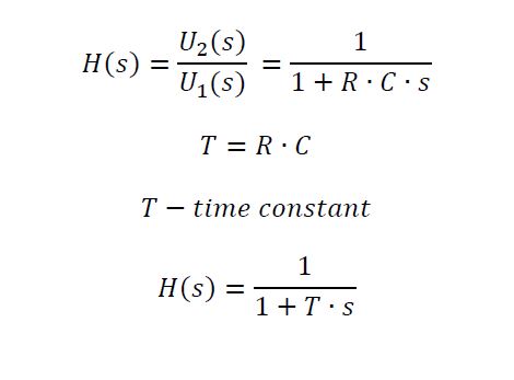
- the first dynamic model as circuit’s transfer function H(s)
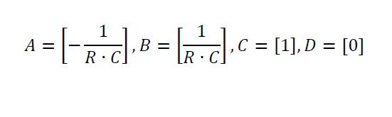
- the second dynamic model as circuit’s state space representation
The input signal in the considered circuit is voltage u_1(t).
The output signal in the considered circuit is voltage u_2(t).
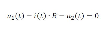
Note that input and output signals are in time domain. Now we write Kirchhoff’s voltage law (KVL) for circuit.
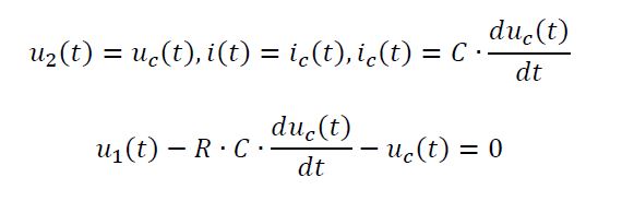
Take into account following relationships and formulas:
Passing to Laplace transformation representation for start conditions equal to zero (ST=0).
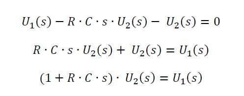
Note that after Laplace transformation domain changed from time t to variable s.
General form of state space representation equations is following:
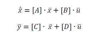
Where:
[A]- state matrix, [B]- input matrix, [C]- output matrix, [D]- feedthrough matrix

The received dynamic models can be used in MATBLAB which has got built in functions for simulating circuits answers. A circuit's answer is understood as a trace/shape/form of circuit's output signal. The MATLAB provides a bunch of functions which allow to simulate variatey of extortions (input signals): an impulse signal, a step signal. It is also possible to plot a Bode diagram.
lsim(l,m,uin,t)
impulse(A,B,C,D)
step(A,B,C,D)
bode(A,B,C,D)