An electirc circuit is examined from the control theory point of view. The examined electric circuit is built from two ideal resistor and one ideal capacitor which according to the electircal engineering theory are passive elements. The input signal of the considered circuit is represented as the input voltage. The output signal is represented as the output voltage. The branch current method will be employed in order to write equations for the electical circuit in the domain of time. Next Laplace transformation will be used on received equations.
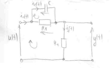
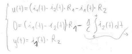
The Kirchhoff's volatge law is employed to write equations for the volatages in the circuit. The considered electic circuitis composed of three meshes, therefore, three volatage equations are written.
In order the designate the transfer function of the considered electirc circuit. All variables, which are time dependant, need to be transformed to the Laplace form i.e. to the domain of a variable s. This is shown below i.e. the input signal u(t) is being transformed to its Laplace equivalent U(s).
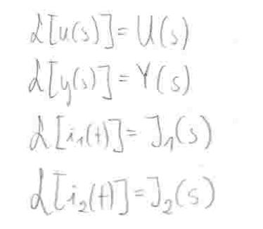
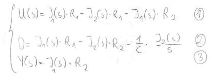
The system of equations of the examined electric circuit is written in the Laplace form.
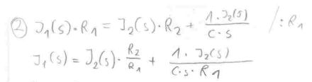
The equation (2) will be rewritten in order to extract the current I1(s).
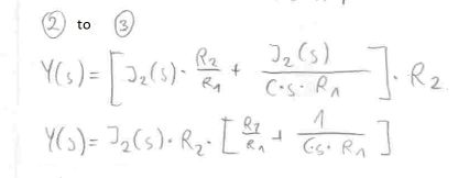
The equation for current I1(s) which has been designated above will replace the current I1(s) in the equation (3).
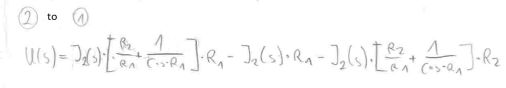
The equation for current I1(s) which has been designated above will replace the current I1(s) in the equation (1).
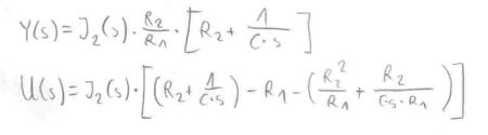
At this point the equations for the input signal Laplace form U(s) and the output signal Laplace form Y(s) are ready to be used to designate the transfer function G(s) of the examined electric circuit.
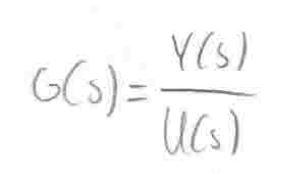
The examined electric circuit transfer function G(s) is a relation equal to the transformed output signal Y(s) divided by the transformed input signal U(s).
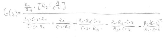
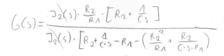
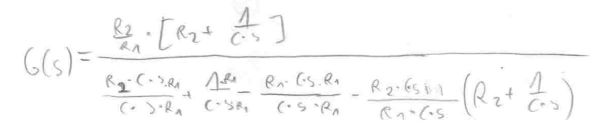
After dividing the equation for the signal Y(s) by the equation for the output signal U(s), the transfer function G(s) has got following form. It should be noted that the current I2(s) can be reduced from the equation.
After the reduction of the current I2(s), the transfer function G(s) has got the following form.
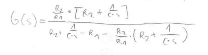
The transfer function G(s) after a small cleanup.
The transfer function G(s) after additional reshuffle in its coefficients. It should be noted that the final form of the equation for transfer function G(s) can be simplified even further by using a relation for time constants in electric circuits i.e. T = R * C [s].