
The electric circuit, which is examined in this example, has two current sources in its topology. The current source is not a branch of a circuit. Obviously the current source is connected to the circuit through wires which have a low resistance r. The resistance r of the current source wires is omitted because it is assumed as close to zero and for a given model of the electrical circuit, it has not got impact on the final results.
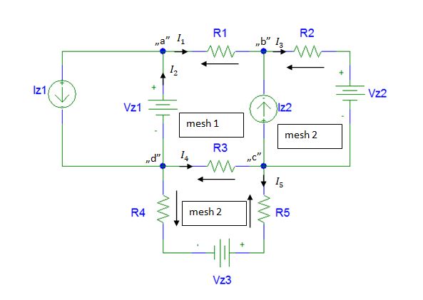
The electric circuit shown on above can be transformed into a different form. The transformed examined electric circuit is present below. The electric circuit after transformation is the equivalent of the circuit before the transformation.
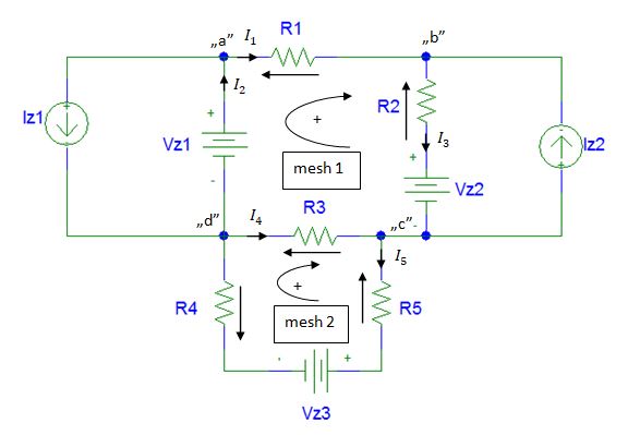
The considered circuit is composed of four nodes and two meshes. In this example the following convention is employed:
- a current which flows to node has sign "+", current which flows out from node has sign "-"
- the voltages which arrows are in the clockwise direction are marked as „+”, the voltages which arrowheads are turned counter-clockwise are marked „-”
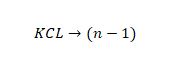
In order to designate the currents and the voltages in an electric circuit the Kirchhoff’s current law equations (KCL) and the Kirchhoff’s voltage law equations (KVL) have to be written down. The number of equations for each Kirchhoff’s law is given by following formulas:
KCL equations=n-1
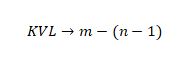
KVL equations=m-(n-1)
n-number of nodes in circuit
m-number of branches in circuit
The number of the nodes is marked n. The number of equations for the Kirchhoff’s current law (KCL) is given by following formula:
In this example, the number of nodes is equal to four (n=4). This means that three Kirchhoff’s current equations are necessary. Redundantly four Kirchhoff’s current equations are written down. To solve the examined electric circuit three current equations from four are needed. In other words, three equations can selected from the set of four Kirchhoff's current law equations.
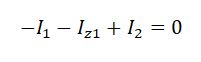
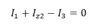
The Kirchhoff’s current law (KCL) equation for node “a”:
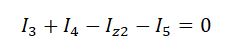
The Kirchhoff’s current law (KCL) equation for node “b”:
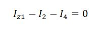
The Kirchhoff’s current law (KCL) equation for node “c”:
The Kirchhoff’s current law (KCL) equation for node “d”:
The number of equations for Kirchhoff’s voltage law (KVL) depends on the number of branches and the nodes in the examined electrical circuit. The general formula for a number of the Kirchhoff’s voltage law (KVL) equations is given below:
where:
m-number of branches
n-number of nodes
The considered electrical circuit has got five branches in its topology. It means that two Kirchhoff’s voltage law (KVL) are needed.
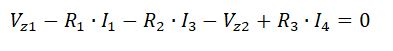
The Kirchhoff’s voltage law (KVL) equation for mesh 1:
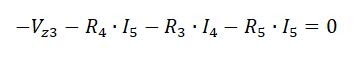
The Kirchhoff’s voltage law (KVL) equation for mesh 2:
Generally speaking, the examined direct current electric circuit is solved. Four equations for the Kirchhoff’s current law (KCL) have been written down. Two equations for the Kirchhoff’s voltage law (KVL) have been written down. Form the electrical engineering point only mathematical computations are necessary to designate numerical values of selected unknowns.