
In electrical AC circuits are a three kinds of power
• apparent power S[V·A]
• active power (real power) P[W]
• reactive power Q[var]
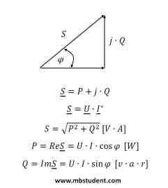
Apparent power S is a geometric sum of active power P and reactive power Q. Active power P (real power) is a power which is possible to convert to mechanical work (mechanical energy) or heat. Reactive power Q is tied with energy transformations in reactive electrical parts like capacitor C or inductivity L. Reactive power Q cannot be converted to mechanical energy or heat. During calculations of power in electrical AC circuits complex numbers are applied. Components of power are represented by vectors on complex variable plane. Vectors of apparent power S, real power P and reactive power create power triangle. In electroenergetic transmission lines quantity of reactive power is minimized because reactive power causes increase of current amplitude. As a result which is related to reactive power transmission, loss on transmission lines resistance increase. Loss on transmission lines resistance Rt_l depends from current in squere → ΔP=I2·Rt_l. Mentioned mechanism of loss explains why electrical energy is transferred on transmission lines by voltage with very high amplitude and current with low amplitude. Electrical energy producers demand from clients to retrieve very low quantity of reactive power. Maximum level of retrieved reactive power is described by minimum cosφ for basic harmonic frequency. Reactive power is possible to produce by client on its own but it has to be compensated.
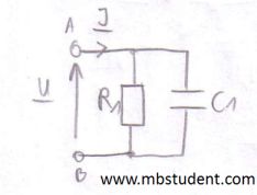
Electrical AC circuit is built with resistor R=10[Ω] and capacitor C=10[mF]. Resistor and capacitor are connected in parallel. Between circuit's power supply terminals is voltage U=100[V]. Voltage has initial phase ψu=π/2. Supply voltage has a frequency f=60[Hz]. As a result of supply voltage, current I flows through circuit. All calculations are made with application of complex numbers. Current I is designated with application of Ohm's law for AC circuits → U=Z·I. To make possible current calculation total impedance Z of circuit has to be designated. Subject of example is calculation of apparent power S, active power (real power) P and reactive power Q. Power triangle is plotted in example.
Power in electrical AC circuit - example 1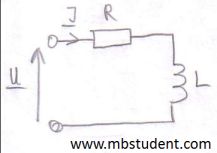
Electrical AC circuit is built with resistor R=0.25[Ω] and inductivity L=10[mH]. Resistor and inductivity are connected in series. Between circuit's power supply terminals is voltage U=230[V]. Voltage has initial phase ψu=π/2. Supply voltage has a frequency f=50[Hz]. As a result of supply voltage, current I flows through circuit. All calculations are made with application of complex numbers. Current I is designated with application of Ohm's law for AC circuits → U=Z·I. To make possible current calculation total impedance Z of circuit has to be designated. Subject of example is calculation of apparent power S, active power (real power) P and reactive power Q. Power triangle is plotted in example.
Power in electrical AC circuit - example 2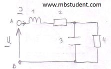
Electrical AC circuit is built with two resistors, capacitor and inductivity. Impedances of all elements are known. Parts in circuit are connected in series and parallel. Current I flows through circuit. Current has starting phase ψi=π/4. Ohm's law for AC circuit is applied to designate circuit's supply voltage U → U=Z·I. Circuit's total impedance Z has to be designated before applying Ohm's law. Subject of example is calculation of apparent power S, active power (real power) P and reactive power Q. Power triangle is plotted in example.
Power in electrical AC circuit - example 3