Category Archives: Electrical engineering

Root mean square value

General formula for RMS – root mean square

F_{RMS} = \sqrt{\frac{1}{T}\int_{0}^{T}{f^{2}(t)\cdot dt}}

The RMS value interpretation based on the electrical current root mean square value.

simple AC electric circuit

W = \int{p \cdot dt}
W = \int{u \cdot i \cdot dt}
W = R\cdot \int{ i^{2} \cdot dt}

where:
W – work
p – temporal electric power
p = u \cdot i
u – temporal electric voltage
i – temporal electric current

If the electrical current is periodical then

W_{T} = R\cdot \int_{0}^{T}{ i^{2} \cdot dt}

Root mean square value of the alternate electric current is an equivalent direct electric current which will produce exactly same amount of heat.

R\cdot \int_{0}^{T}{ i^{2} \cdot dt} = R \cdot I^{2} \cdot T
Dividing both sides of the above equation by resistance R
\int_{0}^{T}{ i^{2} \cdot dt} = I^{2} \cdot T
Next swapping sides in order to find relation for the DC electrical current I
I^{2} \cdot T = \int_{0}^{T}{ i^{2} \cdot dt}
Finally following is received

Root mean square value for the alternate electric current
I_{RMS} = \sqrt{\frac{1}{T}\cdot \int_{0}^{T}{ i^{2} \cdot dt}}

Root mean square value for the alternate electric voltage
U_{RMS} = \sqrt{\frac{1}{T}\cdot \int_{0}^{T}{ u^{2} \cdot dt}}

A maximum power on a load in an electric DC circuit

A series electric DC circuit is being considered to do math. The circuit contains a voltage source with its internal resistance and a load resistors. Resistance of wires is omitted in this example.

A series electric DC circuit

The voltage equation for the circuit above is following
E - R_i \cdot I - R_o \cdot I = 0

Thereby the current is given by the equation
I = \frac{E}{ R_i + R_o }

A general formula for power is
P = U \cdot I

Knowing that the voltage on the resistor Ro is given by the Ohm’s law relation
U(R_o)= I \cdot R_o

A formula for power on the resistor Ro is following
P(R_o)= I^2 \cdot R_o

After plugging in the relation for current
P(R_o)= (\frac{E}{ R_i + R_o })^2 \cdot R_o

The extremum of function P(Ro) needs to be found in order to find which magnitude of the resistor Ro will be give the maximum power.

The first derivative of equation of power on the resistor Ro is following
\frac{dP(R_o)}{dR_o}= \frac{d}{dR_o}((\frac{E}{ R_i + R_o })^2 \cdot R_o)

After doing the math, the theorems for derivatives of the multiplication of functions and internal and external functions were applied
\frac{dP(R_o)}{dR_o}= -2\cdot \frac{E}{ R_i + R_o } \cdot \frac{E}{ (R_i + R_o)^2 } \cdot R_o + (\frac{E}{ R_i + R_o })^2

In order to find the extremum the point where the derivative is equal to 0 needs to be calculated
0= -2\cdot \frac{E}{ R_i + R_o } \cdot \frac{E}{ (R_i + R_o)^2 } \cdot R_o + (\frac{E}{ R_i + R_o })^2

After rearranging the elements in equation above and doing some math
R_o = R_i

Finally, the maximum power on the load resistor Ro is given by formula
P(R_o)_{max} = \frac{E^2}{4 \cdot R_i}

Analysis of an AC electrical circuit

A considered below AC electric circuit is composed of an AC voltage source, a resistor, a capacitor, an AC current source and an inductive coil. The nodal analysis method is being applied to calculate currents in the circuit’s branches. It is recalled that in the nodal analysis method it is always assumed that an electrical potential of one of nodes is equal to 0.

Since the considered electric circuit is an AC circuit following formulas are to be applied:

\underline{Z} = \frac{1}{\underline{Y}} \underline{Y} = \frac{1}{\underline{Z}}
Alternate current electric circuit
\underline{I}_1 \sum{(\underline{I}_s)_a} = \underline{Y}_{R1C1} \cdot \underline{V}_{s1} + \underline{I}_{s2} = \underline{V}_a \cdot ( \underline{Y}_{R1C1} + \underline{Y}_{L1} ) - \underline{V}_b \cdot ( \underline{Y}_{R1C1} + \underline{Y}_{L1} ) \underline{Y}_{R1C1} = \frac{1}{R1 - j \cdot \frac{1}{\omega \cdot C1}} \underline{Y}_{L1} = \frac{1}{\omega \cdot L1}

The further calculations related to the present example are available – Node voltage method example 2.

Total capacitance

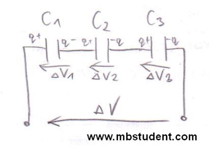
Capacitors connected in series

Capacitance C is a one of basic parameters of electric circuits next to resistance R and inductivity L. Capacitance C is defined as relation of charge Q to voltage V → C=Q/V. The measurement unit of capacitance is Farad → [C]=1F, Farad is a derived unit of SI system. Sometimes it is essential to calculate capacitance of electrical circuit which contains a few capacitors in its topology, therefore, it is often said that total capacitance of electrical circuit is computed. Sometimes during circuits analysis a subject is to calculate the total capacitance which is seen from specific circuit’s terminals.

Total capacitance

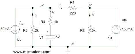
Nodal analysis

Nodal analysis

Nodal analysis is one of methods used for electrical networks analysis. Nodal analysis is based on Kirchhoff’s current law. Main idea of this method is to calculate electrical potentials of every node. This will allow to calculate voltages in branches since voltage is a difference of potentials. This approach has one rule which requires to assume that potential of one chosen node has be equal zero volts. Symbolically this chosen node is connected to the ground on electrical diagram.

Node voltage method

Superposition method – currents calculation in electrical circuit

Electrical DC circuit - superposition method example 1.

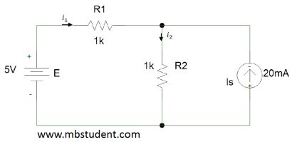
Application of superposition method for simple electrical circuit. Electrical circuit is built from one voltage source and one current source. Main circuit will be divided into two sub-circuits because there are two sources. In the first sub-circuit current source will be the only extortion. In the second sub-circuit voltage source will be the only extortion.

Superposition method in electrical circuit – example 1