State space representation uses state variables for object description. Every state variable is tied with “energy warehouse“. Mechanical and electrical objects have a few types of “energy warehouses”.
Energy warehouses for electrical systems are:
• capacitor C → capacitor stores energy in electric field
• inductivity L → inductivity stores energy in magnetic field
Energy warehouses for mechanical systems are:
• mass m → stores kinetic energy during progressive movement
• inertia I → stores kinetic energy during rotary movement
• mass m → stores potential energy in gravity field
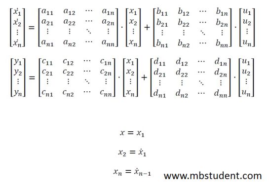
General form of state space representation equations

On this website are placed solved examples in which state space representation and transfer functions are designated for various system. Designating two kinds of dynamic models allows to compare them. Examples placed here contain also sample codes for using with MATLAB. Using mentioned sample codes it is possible to simulate system behavior and plot various characteristic like step response, impluse response and frequency plots.
State space representation for RC circuit – example 1
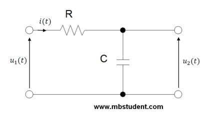
A state space representation and a transfer function designating for a low-pass filter. The low-pass filter is an electric circuit which contains a resistor and a capacitor. The resistor and the capacitor are connected in series. Input voltage(input signal) is between resistor and capacitor. Output voltage(output signal) is capacitor’s voltage. One of capacitor’s terminals is connected to the ground.
RC circuit – state space representation – example
State space representation for RLC circuit – example 1

State space representation and transfer function designating for RLC circuit. Circuit has in its topology: inductivity, capacitor and resistor. All elements are connected in series. Input voltage is between start and end terminals in circuit. Output voltage is voltage on capacitor. One of capacitor terminals is connected to the ground.
RLC circuit – state space representation – example 1
State space representation for RLC circuit – example 2
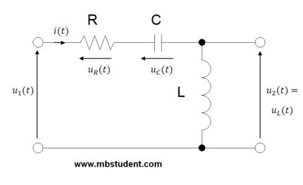
State space representation and transfer function designating for RLC circuit. Circuit has in its topology: inductivity, capacitor and resistor. All elements are connected in series. Input voltage is between start and end terminals in circuit. Output voltage is voltage on inductivity. One of inductivity terminals is connected to the ground.
RLC circuit – state space representation – example 2
State space representation for RLC circuit – example 3
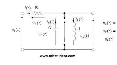
State space representation and transfer function designating for RLC circuit. Circuit has in its topology: inductivity, capacitor and resistor. Inductivity and capacitor are connected in parallel. One of common terminals of capacitor and inductivity is connected in series with resistor. Second common terminal of capacitor and inductivity is connected to the ground. Input voltage is between start and end terminals in circuit. Output voltage is voltage on inductivity and capacitor. Because these elements are connected in parallel their voltages are equal. Characteristic of elements connected in parallel is that they have equal voltages.