You can find here a lot examples from electrical engineering and electrical circuits. Every example is solved step by step. Electrical engineering is a strict science which examines and applies in practice electromagnetism phenomenons. Electromagnetism is a branch of physics. In electrical engineering we use various methods for electrical network analysis. The most basic laws, which are applied in electrical engineering, are Ohm’s law and Kirchhoff’s laws.
Branch current method examples
Collection of exercises where Kirchhoff’s current law (KCL) and Kirchhoff’s voltage law (KVL) are used. Kirchhoff’s law for electrical circuits were formed by German scientist Gustav Kirchhoff. Kirchhoff’s law for electrical circuits are nothing other like the principle of charge conservation and the principle of energy conservation. Both mentioned principles are formed in way useful in electrical circuits.
Kirchhoff’s current law (KCL) tell us that sum of currents which flow to and flow out from node is equal to zero. Kirchhoff’s current law came from the principle of electric charge conservation. We apply Kirchhoff’s current law we use convention that currents which flow to node are with sign “+” and currents which flow out from node are with sign “-“.
Kirchhoff’s voltage law (KVL) tell us that sum of voltages in specified mesh is equal to zero. Kirchhoff’s voltage law came from the principle of energy conservation. Application of Kirchhoff’s voltage law is following. In specified mesh we mark a direction of voltages circulation. When voltages in mesh has equal direction we give them sign “+” otherwise we give them sign “-“.
Superposition method examples
Superposition is one of method for resolving electric circuits. General principle of superposition to examine how single extortions affect circuit. Final result of superposition is sum of effects from single extortions. Superposition is widely used in various field of science. In electrical circuits extortions which we may meet are voltage sources or current sources. When we consider circuit from single extortion the rest of extortions are short circuited or disconnected. Principle of conduct is following:
• voltage sources are being short circuited
• current sources are disconnected
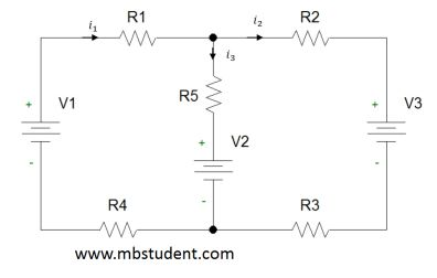
Node voltage method

Node voltage method is one of methods used for electrical network analysis. Node voltage method is based on Kirchhoff’s current law. We can say that node voltage method does not see physical voltage sources. In node voltage method we have to transform all voltage sources to virtual current sources. Additional important rule of node voltage method is that we have to assume that one of node has electric potential equal to zero. On schematics we mark it by connecting symbol of ground to chosen node.
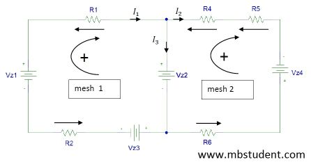
Mesh current method examples

Mesh current method is one of basic method for solving electrical circuits. Mesh current method is one of method used for electrical network analysis. Mesh current method is based on Kirchhoff’s voltage law. It means that this mesh current method sees only voltage sources. If in circuit is a current source we have to transform it to virtual voltage source.
Resistance examples

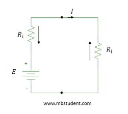
Exercises in which total resistance of electrical circuits is calculated. In some exercises relation between resistance R[Ω] and conductance G[S] is applied → G=1/R. In DC electrical circuits analysis we often have to calculate its total resistance which is seen from power supply terminals. Knowledge about total resistance value is necessary to calculate value of current which flows through circuit. Value of main current which flows through circuit can be calculated with application of Ohm’s law → I=U/R.
Impedance examples

Calculating total impedance Z in AC circuits. In collection of examples you can find derivation of formulas for capacitive reactance and inductive reactance. Impedance is wider magnitude than resistance. Impedance has three components which are: resistance, capacitive reactance and inductive reactance. Impedance in general case is a vector. Components of impedance are geometric sum, because they also are vectors. We use complex numbers to calculate impedance and its components.
Capacitance of electrical circuits
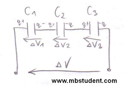
Capacitance C is a one of basic parameters of electric circuits next to resistance R and inductivity L. Capacitance C is defined as relation of charge Q to voltage V → C=Q/V. The measurement unit of capacitance is Farad → [C]=1F, Farad is a derived unit of SI system. Sometimes it is essential to calculate capacitance of electrical circuit which contains a few capacitors in its topology, therefore, it is often said that total capacitance of electrical circuit is computed. Sometimes during circuits analysis a subject is to calculate the total capacitance which is seen from specific circuit’s terminals.
Capacitance of electrical circuits
Transient states
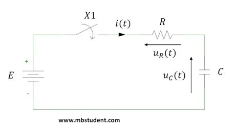
Example electrical circuits in which transient states are examined. In this series of examples differential equations and Laplace transformations are used. Formulas for charging and discharging currents during transient states of circuits with capacitors and inductors are possible to find. In previously considered examples it was assumed that states of electrical circuits were not transient. If an electrical circuit is examined during transient state then commutation laws have to be applied.
Transient states in electric circuits
Power in DC circuits – examples

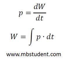
Collection of exercises which are about power P in electrical DC circuits. In DC circuits formula for power is quite simple because it is a multiply of voltage U and current I → P=U·I. Power in electrical DC circuits represents heat produced on resistance R or mechanical energy in electrical motors. Power is a measure how work W is changing in time → P=W/t. Unit of power P is Watt → [W]. Temporary power p is defined as p=dW/dt. From formula for temporary power p, a formula work is possible to designate → W=∫p·dt. Unit of work W is Joule [J]=[W·s].
Power in DC circuits – examples
Power in AC circuits – examples
In electrical AC circuits are a three kinds of power
• apparent power S[V·A]
• active power (real power) P[W]
• reactive power Q[var]
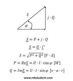
Apparent power S is a geometric sum of active power P and reactive power Q. Active power P (real power) is a power which is possible to convert to mechanical work (mechanical energy) or heat. Reactive power Q is tied with energy transformations in reactive electrical parts like capacitor C or inductivity L. Reactive power Q cannot be converted to mechanical energy or heat. During calculations of power in electrical AC circuits complex numbers are applied. Components of power are represented by vectors on complex variable plane. Vectors of apparent power S, real power P and reactive power create power triangle. In electroenergetic transmission lines quantity of reactive power is minimized because reactive power causes increase of current amplitude. As a result which is related to reactive power transmission, loss on transmission lines resistance increase. Loss on transmission lines resistance Rt_l depends from current in square → ΔP=I2·Rt_l. Mentioned mechanism of loss explains why electrical energy is transferred on transmission lines by voltage with very high amplitude and current with low amplitude. Electrical energy producers demand from clients to retrieve very low quantity of reactive power. Maximum level of retrieved reactive power is described by minimum cosφ for basic harmonic frequency. Reactive power is possible to produce by client on its own but it has to be compensated.